I recently decided to weekly back up some important data. In order to do so, I took an old dusty laptop from the shelf and configured it to wake up with a Wake-On-LAN packet and bought a SATA to USB adapter to plug in an external hard drive.
My typical hard drives are 3.5 inches disks which require both 5V and 12V as power input, hence why most adapters will provide a USB input to do the data transfer and an extra power plug for the 12V. Things would be easier with 2.5" drives (either mechanical or SSD) as they can be powered only with the 5V from USB.
The issue I've been facing was that when the laptop finished copying data and went to sleep, the hard drive would still be powered, and the only way to turn it off is to manually switch the power button on the disk adapter… how convenient for an automated backup solution.
This was unacceptable, and I could not understand why would anyone power on the disk plugged to the adapter if no USB was connected to it. It is still a mystery, but I quickly thought I could easily hack it to only turn on the 12V power when there is any activity on the USB port (i.e. when the laptop is powered on!). That's how my quest to replace a physical toggle switch into an automated solution on a budget started.
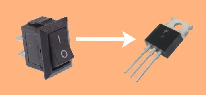 Let's remove the switch in favor of a transistor
Scrapping
I did not want to buy any component online, just scrap any transistor from whatever card I had and do something with it. And so it began, I found an old motherboard dead due to a lightning strike power surge many years ago, identified some transistors that seemed usable from their datasheet online (i.e. have proper input voltages and V(GS)) and started unsoldering it:
 Half-scrapped transistors on a motherboard showing my poor unsoldering skills
Did I forget to mention I only have a basic soldering iron and a cheap desoldering pump with me? You can see it's pretty much a failure, so I decided to take things in hands:
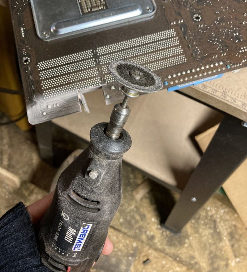 A motherboard that was just cut with a Dremel rotary saw
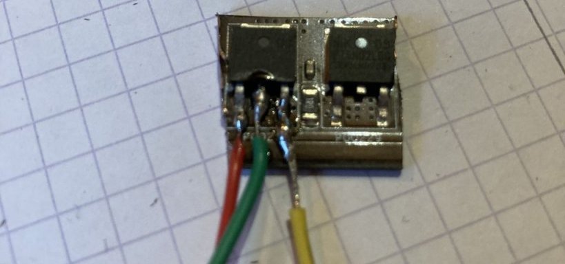 A piece of motherboard with two transistors and their pins soldered to wires
Thanks to my dear friend Dremel, it took me only a few minutes to get things ready.
Soldering it together
Here is a basic schema of the adapter card. The important thing here is that the hardware switch is physically very accessible, but on the schema it is located before the load.
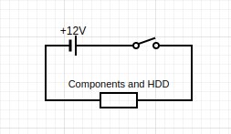 Electronic schema of the current SATA adapter
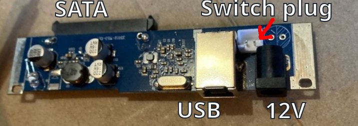 A photo of the SATA to USB adapter
I wanted first to simply replace the switch itself with a transistor, but in my case I only had an N MOSFET P75N02LDG. Thanks to this discussion, I figured out it would not be possible to do so with a transistor placed before the charge, and wouldn't be able to make a high side switch.
So I needed to do place the transistor after the load, and use it as a low side switch, resulting in the following schema:
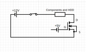 Electronic schema of the planned modifications for the SATA adapter
This sounded harder than simply replacing the switch with an already available plug, as I would need to find the place where all components go to ground and make it go through my transistor. The only way I found was to desolder the power plug and place my transistor between the board ground and the power plug negative socket.
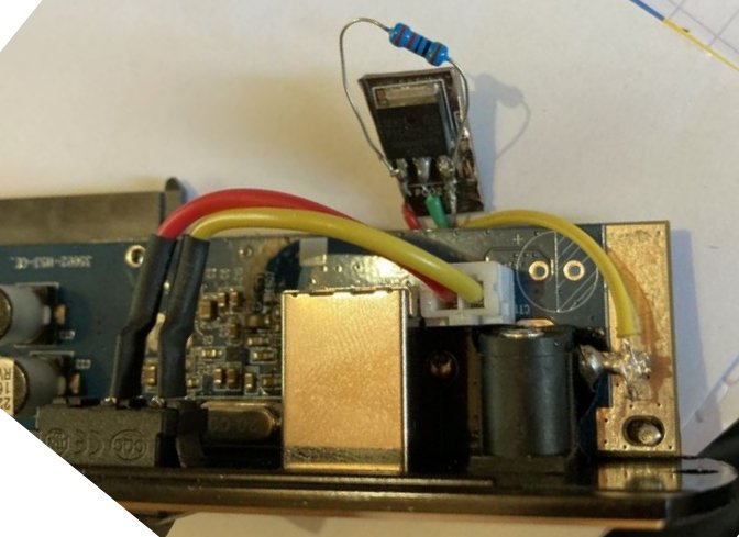 Front side of the SATA adapter with a soldered transistor acting as a low side switch
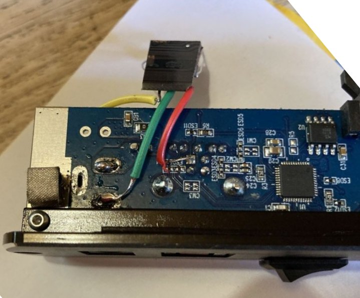 Back side of the SATA adapter with a soldered transistor acting as a low side switch
Now the transistor's gate G (red) is soldered to the USB 5V, the drain D (green) is soldered to the card "ground" after all load, and the source S (yellow) is soldered to the power plug negative side. I also added a resistor between the gate and the source in order to make sure it deactivates when there is no more power on the USB side. Below is the final result:
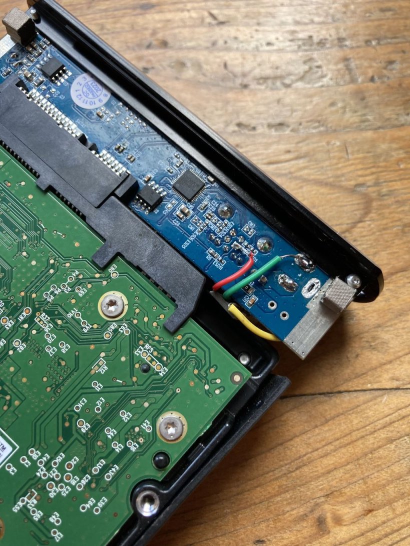 Hacked SATA adapter plugged into a hard drive
Voilà, now my hard drive turns off and on at the same time as my laptop! I'm pretty sure there were better alternatives, however I'm glad I could do what I wanted with what I had!
References: